IoT Workshop
WORKSHOP MANUAL
Intro to IoT & Robotics
Welcome to our IoT and Robotics Network! 🤖🌐 We're all about cool gadgets and smart robots! Join us for workshops where you can learn how to make things that can talk to each other (that's IoT) and build awesome robots that move and do cool stuff.
BASICS OF ARDUINO
Arduino programs are written in the Arduino Integrated Development Environment (IDE). Arduino IDE is a special software running on your system that allows you to write sketches (synonym for program in Arduino language) for different Arduino boards. The Arduino programming language is based on a very simple hardware programming language called processing, which is similar to the C language. After the sketch is written in the Arduino IDE, it should be uploaded on the Arduino board for execution.
The first step in programming the Arduino board is downloading and installing the Arduino IDE. The open-source Arduino IDE runs on Windows, Mac OS X, and Linux. Download the Arduino software (depending on your OS) from the official website and follow the instructions to install.
STEPS TO WORK IN ARDUINO IDE:
Step 1 − Download Arduino IDE Software.
You can get different versions of Arduino IDE from the Download page on the Arduino Official website.
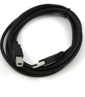
Step 2 − Power up your board using standard USB cable
The Arduino Uno, Mega, Duemilanove and Arduino Nano automatically draw power from either the USB connection to the computer or an external power supply. Connect the Arduino board to your computer using the USB cable. The green power LED (labeled PWR) should glow.Arduino needs 5V power supply.
Step 3 − Launch Arduino IDE.
After your Arduino IDE software is downloaded, you need to unzip the folder.
Inside the folder, you can find the application icon with an infinity label (application.exe). Double-click the icon to start the IDE.
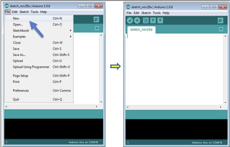
Step 4 To create a new project, select File → New.
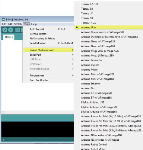
Step 6 − Select your Arduino board.
To avoid any error while uploading your program to the board, you must select the correct Arduino board name, which matches with the board connected to your computer.
Go to Tools → Board and select your board.
 Step 7 − Select your serial port.
Select the serial device of the Arduino board. Go to Tools → Serial Port menu. This is likely to be COM3 or higher (COM1 and COM2 are usually reserved for hardware serial ports). To find out, you can disconnect your Arduino board and reopen the menu, the entry that disappears should be of the Arduino board.
Reconnect the board and select that serial port.
Step 8 − Upload the program to your board.
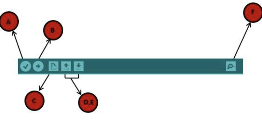
Before explaining how we can upload our program to the board, we must demonstrate the function of each symbol appearing in the Arduino IDE toolbar.
-
− Used to check if there is any compilation error.
-
− Used to upload a program to the Arduino board.
-
− Shortcut used to create a new sketch.
-
− Used to directly open one of the example sketch.
-
− Used to save your sketch.
-
− Serial monitor used to receive serial data from the board and send the serial data to the board.
Now, simply click the "Upload" button in the environment. Wait a few seconds; you will see the RX and TX LEDs on the board, flashing. If the upload is successful, the message "Done uploading" will appear in the status bar.
Once the installation is done you can start creating a blank program which is called as ‘sketch’ in Arduino. The structure of Arduino program is pretty simple. Arduino programs have a minimum of 2 blocks, Preparation and Execution block. Each block has a set of statements enclosed in curly braces:
Here, setup ( ) is the preparation block and loop ( ) is an execution block. The setup function is the first to execute when the program is executed, and this function is called only once. The setup function is used to initialize the pin modes and start serial communication. After the setup ( ) function is executed, the execution block runs next. The execution block hosts statements like reading inputs, triggering outputs, checking conditions etc.
In the above example loop ( ) function is a part of execution block. As the name suggests, the loop( ) function executes the set of statements (enclosed in curly braces) repeatedly.
INTRODUCTION TO TINKERCAD
- Create a Tinkercad Account and Create a New Project

- Click join now and follow online instructions to create an account. Select Create a personal account.
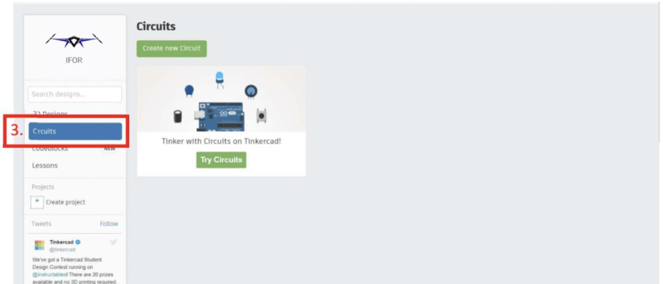
Create New Circuit Project

- Select the Circuits option and Create new Circuit.
-
This space is where we will place all the components. The components can be moved around, edited, and wired together.
-
This section holds all the components. Scroll down to access component types
-
Use this tab to rotate, delete, undo or redo. It also helps users to create and name labels for components.
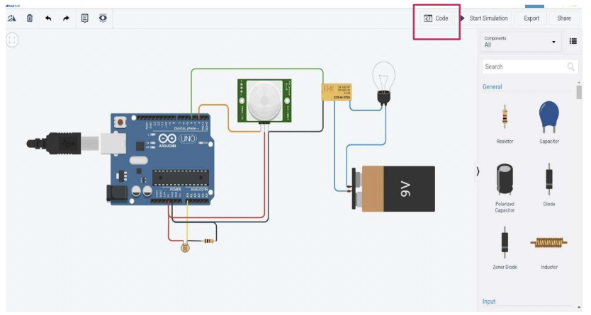
-
This option helps you program Arduino, use serial monitor, start real time simulation, export code, and share your projects.
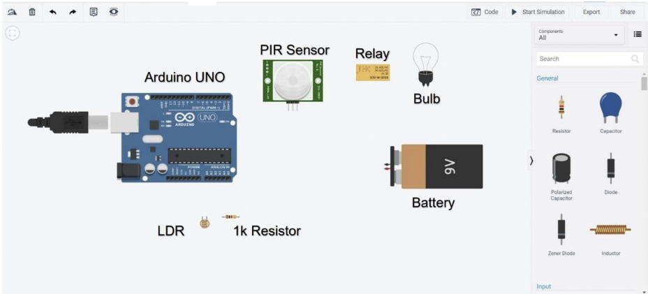
Building the Circuit
-
Place all the components as in the image above by selecting them from the components section on the right side. Click on the component to select and click again anywhere on the workspace to place.
-
Hover over the points of the module to know the output name and click it to start wiring the components.
10.While wiring click the following to bend the wire.
11.Click on wire to select the wire color. This helps in differentiating between wire use. For example, 5v wire color is Red and for GND(Ground) wire color is Black.
12.Once all the wiring has been don click simulation to start the simulation
13.Once wiring is complete, select the code option to start coding.
14.Use the Text option to write the code for this tutorial or use block coding.
EXERCISE 1:
SPEED CONTROL OF SERVO MOTOR
WHAT IS SERVO MOTOR:
A servo motor consists of a small electric motor, a potentiometer, control electronics, and a gearbox. The position of the output shaft is constantly measured by the internal potentiometer and compared with the target position set by the controller -Arduino. The gearbox decreases the speed of the motor, which increases the torque at the output shaft.
SERVO MOTOR SPECIFICATIONS :
- Operating speed: 0.12second/ 60degree ( 4.8V no load)
- Stall Torque (4.8V): 17.5oz /in (1kg/cm)
- Operating voltage: 3.0V~7.2V
- Temperature range: -30 to +60
- Dead band width: 7usec
CONTROLLING A SERVO MOTOR:
Servo motors are controlled by sending a PWM (pulse-width modulation) signal to the signal line of the servo. The width of the pulses determines the position of the output shaft. When a signal with a pulse width of 1.5 milliseconds (ms)is sent , the servo will move to the neutral position (90 degrees). The min (0 degrees) and max (180 degrees) position typically correspond to a pulse width of 1 ms and 2 ms respectively.
RUN 1: TINKERCAD/ARDUINO CIRCUIT DIAGRAM:
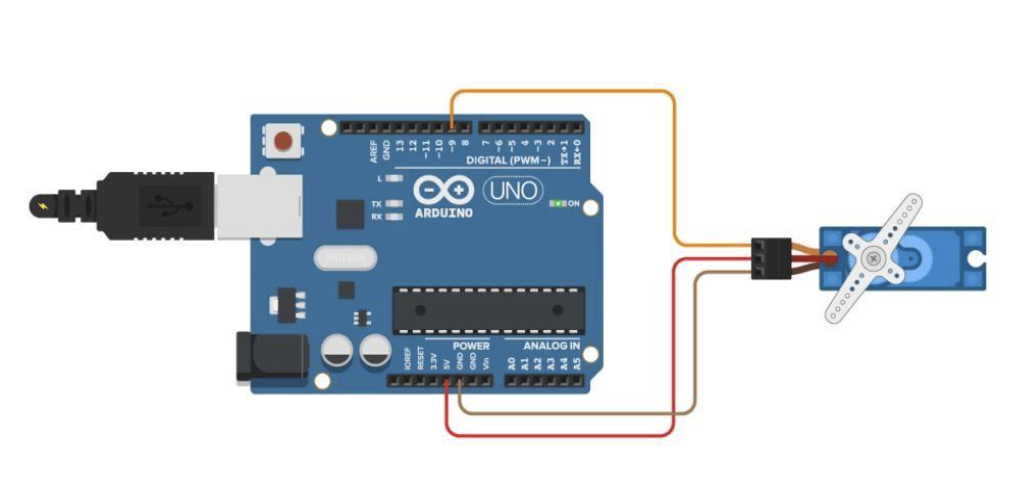
WIRING TABLE:
| Servo motor | Arduino |
|---|---|
| Power(red) | 5V |
| Ground(black or white) | GND |
| Signal(yellow, orange or white) | Pin 9 |
ARDUINO CODE:
Servo motor with Arduino example code. Position and sweep. More info: https://www.makerguides.com/
//Include the servo library:
include <Servo.h>

//Create a new servo object:
Servo myservo;

//Define the servo pin:
define servoPin 9

//Create a variable to store the servo position:
int angle = 0;
void setup()
{
    //Attach the Servo variable to a pin:
    myservo.attach(servoPin);
}

void loop()
{
    //Sweep from 0 to 180 degrees:
    for (angle = 0; angle <= 180; angle += 1)
    {
        myservo.write(angle);
        delay(15);
    }

    //Delay after reaching 180 degrees
    delay(1000);

    //Sweep back from 180 to 0 degrees:
    for (angle = 180; angle >= 0; angle -= 1)
    {
        myservo.write(angle);
        delay(15);
    }
    //Delay after reaching 0 degrees
delay(1000);
}
RUN 2:
POSITION CONTROL OF SERVOMOTOR WITH POTENTIOMETER
In this example, we will use the potentiometer to control the servo motor position. The original idea is that when we change the potentiometer value, the Arduino will reference this value and drive the motor to the desired position.
TINKERCAD/ARDUINO CIRCUIT DIAGRAM:
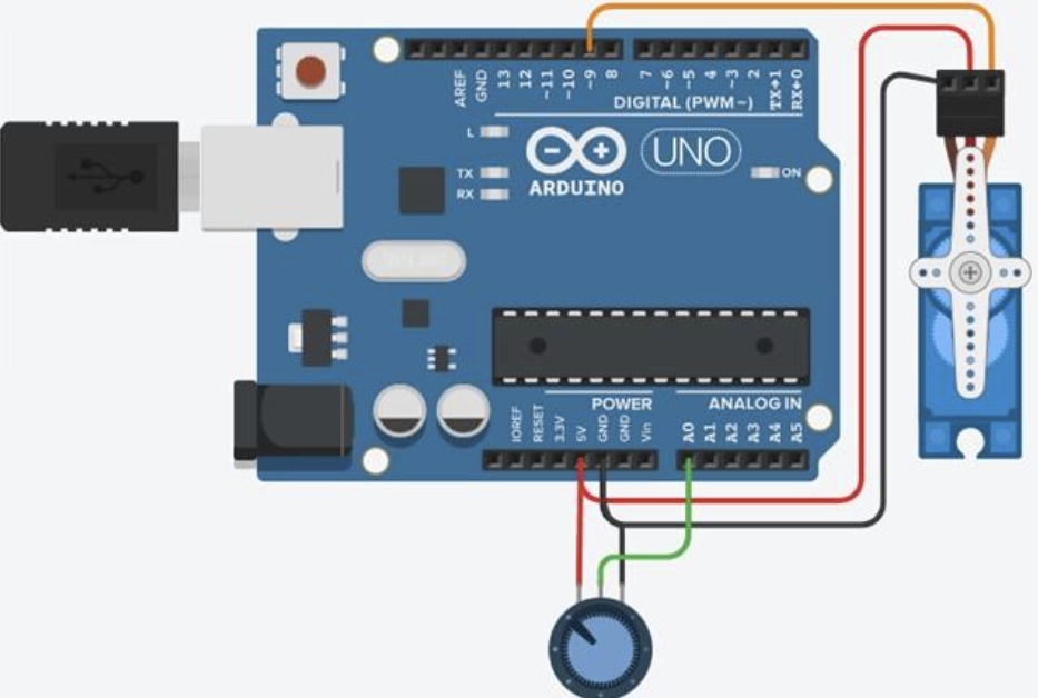
WIRING TABLE:
| Servo motor | Arduino |
|---|---|
| Power(red) | 5V |
| Ground(black or white) | GND |
| Signal(yellow,orange or white) | Pin 9 |
| Potentiometer | Arduino |
| Middle pin | A0 |
| Other two pins | 5V and GND (any order) |
ARDUINO CODE:
include <Servo.h>
Servo myservo; //Create a new object of the Servo class*

int angle = 0;  //Variable to store the servo position in degrees*
int potPin = A0; //Pin connected to the potentiometer*
int reading = 0; //Variable to store the reading from the analog input*

void setup()
{
    myservo.attach(9);
    //Pin 9 of Arduino connected to the control wire of the servo motor*
}

void loop()
{
    *reading = analogRead(potPin);
    //Read the analog input fro the potentiometer*

    *angle = map(reading, 0, 1023, 0, 180);
    //Map the input to a value between 0 and 180 degrees*

    *myservo.write(angle);
    // Set the servo to the calculated angle*

    *delay(15);
    // Wait for the servo to reach the position*
}
EXERCISE 2 : OBSTACLE DETECTION USING ULTRASONIC SENSOR HC-SR04 BUZZER AND LED
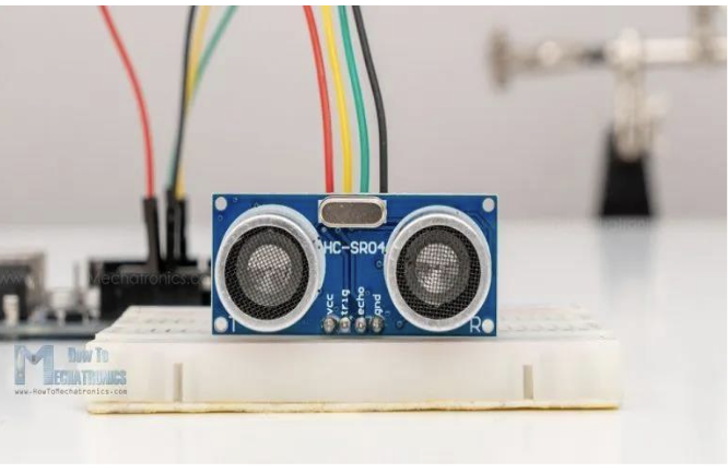
ULTRASONIC SENSOR HC-SR04 OVERVIEW:
The HC-SR04 is an affordable and easy to use distance measuring sensor which has a range from 2cm to 400cm (about an inch to 13 feet). The sensor is composed of two ultrasonic transducers. One is transmitter which outputs ultrasonic sound pulses and the other is receiver which listens for reflected waves. It’s basically a sonar which is used in submarines for detecting underwater objects.
Specification of HC-SR04:
| Operating Voltage | 5V DC |
|---|---|
| Operating Current | 15mA |
| Operating Frequency | 40KHz |
| Min Range | 2cm / 1 inch |
| Max Range | 400cm / 13 feet |
| Accuracy | 3mm |
| Measuring Angle | <15° |
| Dimension | 45 x 20 x 15mm |
HC-SR04 Ultrasonic Sensor Pinout
Here’s the pinout of the sensor:
The sensor has 4 pins. VCC and GND go to 5V and GND pins on the Arduino, and the Trig and Echo go to any digital Arduino pin. Using the Trig pin we send the ultrasound wave from the transmitter, and with the Echo pin we listen for the reflected signal.
RUN1:
HC-SR04 ULTRASONIC SENSOR WITH BUZZER AND LED:
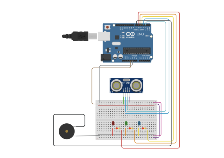
WIRING TABLE:
| Ultrasonic Sensor | Arduino |
|---|---|
| Vcc | 5V |
| Trig | Pin 3 |
| Echo | Pin 2 |
| Gnd | GND |
| Buzzer | Arduino |
| + | 5V |
| - | Pin 7 |
| (RGB) Led | Arduino |
| Cathode (-) | GND |
| Anode (+) | Pin 6, 5, 4 through resistor |
ARDUINO CODE:
const int echoPin = 2, triggerPin = 3, redPin = 6, greenPin = 5, bluePin = 4;
const int buzzPin = 7;
int pulseValue;
float distance;

void setup()
{
    pinMode(echoPin, INPUT);
    pinMode(triggerPin, OUTPUT);
    pinMode(redPin, OUTPUT);
    pinMode(greenPin, OUTPUT);
    pinMode(bluePin, OUTPUT);
    pinMode(buzzPin, OUTPUT);
    Serial.begin(9600);
}

void loop()
{
    digitalWrite(triggerPin, LOW);
    delayMicroseconds(5);
    digitalWrite(triggerPin, HIGH);
    delayMicroseconds(10);
    pulseValue = pulseIn(echoPin, HIGH);
    distance = (pulseValue * 0.0001657 * 39.37);
    if (distance <= 10 )
    {
        digitalWrite(redPin, HIGH);
        digitalWrite(greenPin, LOW);
        digitalWrite(bluePin, LOW);
        tone(buzzPin, 500);
        delay(1000);  // Delay for 2 seconds
    }

    else if (distance <= 30 && distance > 10)
    {
        digitalWrite(redPin, LOW);
        digitalWrite(greenPin, HIGH);
        digitalWrite(bluePin, LOW);
        tone(buzzPin, 1000);
        delay(1000);  // Delay for 2 seconds
    }

    else if (distance >30)
    {
        digitalWrite(redPin, LOW);
        digitalWrite(greenPin, LOW);
        digitalWrite(bluePin, HIGH);
        tone(buzzPin, 1500);
        delay(1000);  // Delay for 2 seconds
    }

Serial.print("Distance: ");
Serial.print(distance);
Serial.println(" inches");
delay(500);  // Delay between measurements
}